I have that exact one, but removed it when I fitted a UK speedo.

I have been wondering if it can be used JUST as a delimiter in conjunction with UK speedo by wiring in after the speedo rather than before.
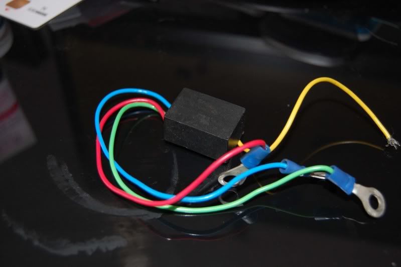
I have managed to determine the wires are as follows:
yellow: km/h speed input from gearbox
Blue
- mph speed output to speedo
red
-
+12v
green
- GND
grey
-
'ECU out'
- not needed for mr2 import clocks as by converting km/h to mph you in effect set the limiter to 180mph.
Possibly used for standalone delimiting?
To install:
Remove instrument binnacle
When viewed from behind, locate the 4 screws to the speedo.
Wire the blue wire to top Left, red to bottom left and green to bottom right screws using the installed ring bits.
Cut the speedo input signal wire and wire the yellow lead to it.
Trace back from the speedo topleft screw to the wiring loom to locate correct wire.
I
*think* it is the purple/silver dotted one.