About two years ago a couple of people put it into my head to build a control box to add tiptronic functionality to the regular mk2 auto. As I work in electronics I designed a basic control box that gives you full control of the gears...
Anyways I got married, bought a house, sold my car and the project sat in the loft until now.....
I've bought a Rev 3 Auto import (See Here) and the plan is to install a prototype control box to see if tiptronic control of the mre2 gearbox works.
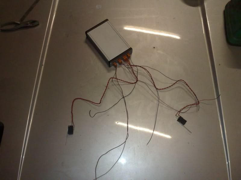
The toyota auto gearboxes are electronically controlled by 3 solenoids.
My plan is to chop into the ecu wiring to install a switch that will let me flip between full auto and the flappy paddles. The control box needs wiring in and I need to find some suitable easy to install paddles and a way to get the signals off the steering wheel without trailing wires!
Anyways, here is the progress so far....
Fitted a 3 pole 2 way switch in a hole that was conviniently left by the previous owner. I'm going to run a 7 core cable to the ecu and splice into the control solenoids wiring for the gearbox. There are two shift solenoids and one torque converter lockup. The last wire will splice into the brake signal (STP) on the ECU so my box knows when to disengage torque converter lockup so you can't stall!
The 3 wires going to the solenoids will run to the centre contact of the switch and the 3 wires from the ecu will run to one of switch contacts (not sure which yet). I'll then connect the other contact to the flappy paddle control box which should allow me to switch between the two.
I've bought off ebay an airbag slip ring off a toyota celica as a potential way of getting the wires for the paddles through to the steering wheel.
Whilst in the car today I thought i'd have a look to see how potentially this might fit. Much to my suprise when I took off the horn cover there was already an airbag slip ring fitted connected to the horn, my rev 1 was deffo not configured like this. Have had a little poke around it looks like the connector comes out at the lower rear of the slip ring, however there is a little circuit board in there that i'm not sure what it does. Anyone got any info on the airbag system? If I can access the wiring, the 3 pin connector behind the steering wheel will work perfectly for connecting the paddles up to!!
Goldy's MK2 Flappy Paddle Gearbox Build
Moderators: IMOC Moderators, IMOC Committee Members
Re: Goldy's MK2 Flappy Paddle Gearbox Build
Nice idea, I'll be watching this with interest
Stuart
Stuart
I asked God for a bike, but I know God doesn't work that way. So I stole a bike and asked for forgiveness.
Re: Goldy's MK2 Flappy Paddle Gearbox Build
I've had a little fettle round, I think i've worked out the pinout for the ecu. The rev3 auto ecu is different than the 3SFE one from the MR2 tech BGB. This is bodged together from some info from the celica forums and a wiring diagram from the REV 3 3SGE bgb.
I had a quick check with a multimeter, B+, Batt and E1 are all in the correct positions. S1 can be checked, it should be = battery voltage with ignition on and 0v with ignition off, SL and S2 should be 0V with ignition on or off.
The three wires under my thumb correspond to the three control solenoids for the auto box, i'm going to try to check the wiring colours to double check i've got the right wires before I cut anything.
Next up is to splice into S1 S2, SL and STP and run them via 7 core trailer cable (from maplin) to the cockpit.
-
- Posts: 833
- Joined: Sat Dec 12, 2009 2:59 am
- Location: Scotland
Re: Goldy's MK2 Flappy Paddle Gearbox Build
Very interesting thread m8
would the rev1 be much different (n/a rev1 auto)
Richie
would the rev1 be much different (n/a rev1 auto)
Richie
Re: Goldy's MK2 Flappy Paddle Gearbox Build
The gearbox and electronic control system is the same as far as i'm aware. The ecu pinout would be different for a rev1. The steering wheels on the rev1 also don't have the 3 pin connector as far as i'm aware.
The gearbox is simply controlled by two solenoids which are controlled by the ecu. These determine which gear is selected when in drive. There is also a lockup solenoid which locks up the torque converter when cruising in overdrive.
Below is the page from the BGB :
And the earlier ecu pinout (3SFE)
The gearbox is simply controlled by two solenoids which are controlled by the ecu. These determine which gear is selected when in drive. There is also a lockup solenoid which locks up the torque converter when cruising in overdrive.
Below is the page from the BGB :
And the earlier ecu pinout (3SFE)
Re: Goldy's MK2 Flappy Paddle Gearbox Build
I've run the 7 core cable from the ecu to the switch next to the gearlever.
I took the plunge and snipped the wires...... Stated the car up and took it for a drive, D was overdrive as per the BGB specs when the solenoids are disconnected, so it appears those are the correct wires. The car didn't throw any fault lights which is a bonus.
I've soldered the wires onto the switch in my dashboard... The 3 wires from the ecu go to one side of the switch, the 3 wires from the solenoids go to the centre of the switch and the other 3 contacts will connect to my control box.
I decided to put the control box in the glovebox for the moment, for ease of access, this means I can update the firmware without having to take too much stuff apart. As well as this there was a handy hole in the side of the glovebox to run the wires.
I thought I should take it for a little test to see if the switch works. As soon as I got out onto the road I knew something was wrong. The geabox was stuck in either 3rd or overdrive no matter what position the switch was in .
I checked the continuity at the switch and ecu with a multimeter; one of the wires wasn't connected.... it turns out my colourblindness meant I had wired up solenoid 1 to the red wire instead of the brown . A quick swap round and the second road test was fine. The car works in full auto with the switch off and sits in overdrive with the switch on !
I've put the geartrim all back together.... next step is to get some power wired up to the box and to build some paddle shifters!
-
- Posts: 833
- Joined: Sat Dec 12, 2009 2:59 am
- Location: Scotland
Re: Goldy's MK2 Flappy Paddle Gearbox Build
Goldy wrote:The gearbox and electronic control system is the same as far as i'm aware. The ecu pinout would be different for a rev1. The steering wheels on the rev1 also don't have the 3 pin connector as far as i'm aware.
The gearbox is simply controlled by two solenoids which are controlled by the ecu. These determine which gear is selected when in drive. There is also a lockup solenoid which locks up the torque converter when cruising in overdrive.
Cheers Goldy. I will be keeping an eye on this it's looking very promising, you are doing it for the Auto owners
keep up the goooooooood work buddy.
Richie
Re: Goldy's MK2 Flappy Paddle Gearbox Build
This is awesome! Best of luck with this
Re: Goldy's MK2 Flappy Paddle Gearbox Build
If there was a smiley that took his hat off, I would post it.
Re: Goldy's MK2 Flappy Paddle Gearbox Build
Amelio wrote:If there was a smiley that took his hat off, I would post it.
Re: Goldy's MK2 Flappy Paddle Gearbox Build
I've been looking around for a standard steering wheel with flappy paddles or buttons to fit and so far have come up with nothing. I think the Celica or MRS tiptronic wheels may possibly fit and would look nice and factory. However I want some paddles so I decided to have my own attempt....
I've cut a chunk out of the steering wheel cowl and stuck two microswitches in there..... I think it's a reasonable start.... I need to get them mounted a bit more permenently as they're just held in with a single self tapper at the moment.
To get the horn back on I had to trim the edges of the rubber back, you can see where i've cut one side in the picture below :
Finally I made a cardboard mockup of the flaps, Nik from Zombie Wings is making me some lovely carbon flaps for my prototype...
Re: Goldy's MK2 Flappy Paddle Gearbox Build
Right more progress,
Having taken the steering wheel apart, i've decided that the best option would be to secure the switch to the horn earth contact. This gives me two mounting points and the horn contact can act as the ground connection on the switch. Convieniently the switch contacts mount up amost perfectly.
So i've drilled two 3mm holes in the horn plate, and i've tapped the switch contact so I can screw in an M3 machine screw. Hey presto... two micro switches securely mounted.
I've re-fitted the steering wheel and added my aluminium flap to check the clearance. I think it's about the right size so as not to be too intrusive. Nik is producing some sexy carbon flaps which I think will look the dogs doo daas when fitted
On the subject of wiring the flaps i've decided to fit a different resistor to each switch and the horn. When each button is pushed it will connect that resistor to ground this will give three different voltage levels. Using a comparator I can compare the voltages against a set level to give me three digital outputs. Its very similar to the way that most steering wheel stereo controls seem to work. I'll post up a circuit diagram when i've drawn it!
Does anyone know how much current the horn requires?
Cheers,
Simon
Re: Goldy's MK2 Flappy Paddle Gearbox Build
Another Update..... my carbon flaps from Nik arrived on Saturday. It's nice to see the difference between prepreg carbon fibre and wetlay. The prepreg stuff is much tougher and easier to drill and sand without cracking. The wetlay stuff I used before was a total disaster zone when drilled and sanded.
I've added a bit of shape to the flaps but i'm still not 100% happy with the shape of them yet, i'm planning on adding a white + and - on at some point. I drilled two holes and mounted my plates to attach the flaps to the microswitches.
Then i've mounted them in the car, they fitted fine without issue and there is plenty of cleance to get your hands either side. I think they're just big enough to grab easily but small enough to miss if you place your hand in the wrong bit.
I've put together 50% of the circuit board to get the signals down the horn wire from the steering wheel. I'm a few resistors short so i'll hopefully pick them up tomorrow and maybe i'll get it all working this week (fingers and toes crossed)
-
- Posts: 7068
- Joined: Mon Feb 11, 2008 5:47 pm
Re: Goldy's MK2 Flappy Paddle Gearbox Build
awsome project...
will it be at jae?? would be good to see...
wonder how quick it will change the gears..
well done sir
will it be at jae?? would be good to see...
wonder how quick it will change the gears..
well done sir
MR2 Sprint zombie outbreak response vehicle
https://www.facebook.com/pages/Zombie-S ... 0272127049
https://www.youtube.com/channel/UCNBrEd ... s-qbox0FwQ
https://www.facebook.com/pages/Zombie-S ... 0272127049
https://www.youtube.com/channel/UCNBrEd ... s-qbox0FwQ
-
- IMOC Committee
- Posts: 11345
- Joined: Tue May 30, 2006 5:41 pm
- Location: The Toast Aisle
- Contact:
Re: Goldy's MK2 Flappy Paddle Gearbox Build
On the subject of steering wheels, weren't the VVTi MK4 Supra Autos tiptronic? IIRC they have 4 buttons, 2 front and 2 rear with the front ones being down and the rear ones being up.
IMOC-UK - the only club to win 'Best Club Stand' at JAE more than once, and twice in a row!
Re: Goldy's MK2 Flappy Paddle Gearbox Build
Good work mate
Re: Goldy's MK2 Flappy Paddle Gearbox Build
pistol pete wrote:awsome project...
will it be at jae?? would be good to see...
wonder how quick it will change the gears..
well done sir
Gear changes should be pretty slick. I'll be at JAE so you can have a poke round then
toxo wrote:On the subject of steering wheels, weren't the VVTi MK4 Supra Autos tiptronic? IIRC they have 4 buttons, 2 front and 2 rear with the front ones being down and the rear ones being up.
I've been having a good look for a compatiable steering wheel, I haven't seen even a picture of the Supra Tiptronic wheel never mind one for sale on ebay. Ideally I'd like to fit a standard toyota wheel with paddles
-
- IMOC Committee
- Posts: 11345
- Joined: Tue May 30, 2006 5:41 pm
- Location: The Toast Aisle
- Contact:
Re: Goldy's MK2 Flappy Paddle Gearbox Build
Goldy wrote:
toxo wrote:On the subject of steering wheels, weren't the VVTi MK4 Supra Autos tiptronic? IIRC they have 4 buttons, 2 front and 2 rear with the front ones being down and the rear ones being up.
I've been having a good look for a compatiable steering wheel, I haven't seen even a picture of the Supra Tiptronic wheel never mind one for sale on ebay. Ideally I'd like to fit a standard toyota wheel with paddles
I've never seen a stock Toyota wheel with paddles... Lexus maybe
IMOC-UK - the only club to win 'Best Club Stand' at JAE more than once, and twice in a row!
Re: Goldy's MK2 Flappy Paddle Gearbox Build
toxo wrote:Goldy wrote:
toxo wrote:On the subject of steering wheels, weren't the VVTi MK4 Supra Autos tiptronic? IIRC they have 4 buttons, 2 front and 2 rear with the front ones being down and the rear ones being up.
I've been having a good look for a compatiable steering wheel, I haven't seen even a picture of the Supra Tiptronic wheel never mind one for sale on ebay. Ideally I'd like to fit a standard toyota wheel with paddles
I've never seen a stock Toyota wheel with paddles... Lexus maybe
I've seen a celica, mr2 and a lexus wheel with buttons on but not actual paddles.... I've not found one for sale anywhere yet, even spoke to some Jap car breakers in Hong Kong and they couldn't find one for me!
Re: Goldy's MK2 Flappy Paddle Gearbox Build
Having had the flaps in the car for a week or two, they are wholy unworkable in their current state, the microswitches have far to much play, they feel to flimsy and the flaps stick out too much and catch your hands, i'm thinking about an alternative diy solution but for the moment i've ordered some AMG flaps from mercedes benz, i've seen these used on another diy project so i'll give it a go....
Part number is : A1712670046 circa £120 from Mercedes
They arrived today, I was quite impressed by the quality as I was expecting them to be plastic and quite flimsy but they're actually fully metal and rather weighty good old mercedes benz .
This is how things progressed :
Cut a paper outline then cut a hole in the steering wheel back. Once that was cut, I removed the rubber that was underneath with a stanely knife from the rear of the steering wheel. Using the template I drilled a 4mm hole to attach the paddles....
Repeat + 2 x paddles + 2 x screws = Bobs your uncle.... :icon_cool:
Fitted back in the car :
They don't fit perfectly due to the line of the steering wheel but they look good and feel solid..... just got to sort the final bit where the flaps talk to the control box now