[Mk2] [Turbo] Better air intake temp sensor and positioning.Results page 6.
Moderators: IMOC Moderators, IMOC Committee Members
Re: [Mk2] [Turbo] Better air intake temp sensor and positioning.Results page 6.
Sorry- but drop me a pm and I could do you one 

Re: [Mk2] [Turbo] Better air intake temp sensor and positioning.Results page 6.
Rob - East Coast Imports wrote:
m10x1.25
Is this the size I need to accommodate the standard Mat sensor Rob
Then I can block the hole and leave the rait sensor in the standard mat sensor location and bring the subject up and be able to swap if needed when the car is on the dyno, if not then no harm done.
As Jim says, Toyota put it there for a reason and I don't want to risk an expensive bill by moving it without knowing the consequences.
Thanks
Last edited by Martin F on Wed Oct 07, 2015 9:44 pm, edited 1 time in total.
Re: [Mk2] [Turbo] Better air intake temp sensor and positioning.Results page 6.
standard sensor is M16x1.5, the triumph sensor is M10x1.25
I'd be interested to see how the person that mapped your PFC has set it up to respond to air temp readings, particularly the IGN vs air temp, as the base map isn't set to start pulling timing till 60 degrees(I've set mine lower...)
I'd be interested to see how the person that mapped your PFC has set it up to respond to air temp readings, particularly the IGN vs air temp, as the base map isn't set to start pulling timing till 60 degrees
EX MR2 owner, currently on a '00 Honda CBR600 Follow me on Instagram @c35rob
Re: [Mk2] [Turbo] Better air intake temp sensor and positioning.Results page 6.
Rob - East Coast Imports wrote:standard sensor is M16x1.5, the triumph sensor is M10x1.25
I'd be interested to see how the person that mapped your PFC has set it up to respond to air temp readings, particularly the IGN vs air temp, as the base map isn't set to start pulling timing till 60 degrees
Last map was done at surrey rolling road, no idea of what has been done regarding air temps etc.
Re: [Mk2] [Turbo] Better air intake temp sensor and positioning.Results page 6.
jimGTS wrote:bare in mind, this sensor is called a MAT sensor
a manifold air temperature sensor.
I'm sure theres a very good reason why toyota installed it where they did, as thats the temperature entering the ENGINE.
not the temp inside an intercooler pipe.
Come on mate as if the sensor being being a few inches away from the stock location would really make any real world difference in the temperature being reported back to the ECU.
The old Toyota did this for a reason argument could be applied to anything on the car, why fit after market parts/upgrades etc when Toyota fitted all the stock parts for a reason.
This replacement sensor is a good example in itself.
jimGTS wrote:if the car is stood still, it will heatsoak, there is nothing you can do about this and you want this to read correctly.
That's the precise reason to do something about it, if the sensor is heatsoaked it won't be reading correctly.
With that said getting away from the heatsoak issue will be pretty hard, more of a case of reducing its effect.
there is still going to be a degree of heat soak
I did try to find some technical data on that triumph/sagem sensor but no luck apart from this thread
http://irishrotary.com/forum/index.php? ... nsor-riat/
which quotes the fenne development ad from ebay and provides some resistance values.
Just so others can see at a glance I crudely extrapolated those values onto the resistance/temp graph for a Toyota manifold temp sensor and it looks like this

Which as you rightly said Jim
Re: [Mk2] [Turbo] Better air intake temp sensor and positioning.Results page 6.
tiff_lee wrote:jimGTS wrote:bare in mind, this sensor is called a MAT sensor
a manifold air temperature sensor.
I'm sure theres a very good reason why toyota installed it where they did, as thats the temperature entering the ENGINE.
not the temp inside an intercooler pipe.
Come on mate as if the sensor being being a few inches away from the stock location would really make any real world difference in the temperature being reported back to the ECU.
The old Toyota did this for a reason argument could be applied to anything on the car, why fit after market parts/upgrades etc when Toyota fitted all the stock parts for a reason.
This replacement sensor is a good example in itself.
jimGTS wrote:if the car is stood still, it will heatsoak, there is nothing you can do about this and you want this to read correctly.
That's the precise reason to do something about it, if the sensor is heatsoaked it won't be reading correctly.
With that said getting away from the heatsoak issue will be pretty hard, more of a case of reducing its effect.
there is still going to be a degree of heat soak
I did try to find some technical data on that triumph/sagem sensor but no luck apart from this thread
http://irishrotary.com/forum/index.php? ... nsor-riat/
which quotes the fenne development ad from ebay and provides some resistance values.
Just so others can see at a glance I crudely extrapolated those values onto the resistance/temp graph for a Toyota manifold temp sensor and it looks like this
Which as you rightly said Jim
This is a good read and makes perfect sense.
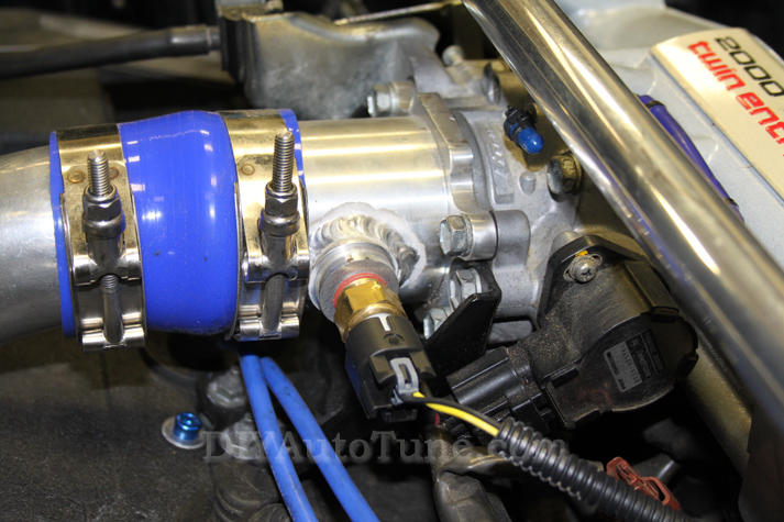
I have just been for a nice long drive, I now have the Rait sensor.
Today the outside temps were 15 degrees, power fc reads 28 degrees when cruising around 65 mph
Parked car up for 15 minutes, came back and as soon as I turn on the ignition it is saying the air temp is bang on 50 degrees, now that figure is before I even start the engine.
So you can't even blame the air flow from the chargecooler, quite possibly it is the air temp around the sensor due to the heat from the pistons etc heating the air around the sensor however it takes quite a while to come back down.
I am moving the sensor to see what happens, I just can't find anywhere that has an aluminum nut in stock m16 x 1.5 so I can weld it in the 45 degree pipe.
I am not going to use the throttle body because it is narrower than the chargecooler pipe and therefore needs all its space for airflow.
will update my findings when the deed is done, would be today if I could find this illusive m16 nut
Re: [Mk2] [Turbo] Better air intake temp sensor and positioning.Results page 6.
I was thinking about this earlier and what I wrote before with regards to the OE sensor.
I was trying to get my head around the difference in speed at which the two sensors report temperature change, given that they are both thermistors so any change in temperature should change the output, it's not as if they are a digital device with a sample rate. Then the obvious struck me, one has the thermistor exposed exposed to air while the oe one is encased in brass so all the brass would need to increase/decrease in temperature hence the slower response but why do that? If late 90s motorbikes had these faster sensors then why not rev4/rev5 mr2s?
Meh be interesting to see your results, from googling it seems alot of people relocate the sensor to the cold start injector location. I would like mine of the cold side of my st205 chargecooler when I get it but I think that's going to be very unlikely due to space constraints, i'll have to assess it when I get it.
I was trying to get my head around the difference in speed at which the two sensors report temperature change, given that they are both thermistors so any change in temperature should change the output, it's not as if they are a digital device with a sample rate.
Meh be interesting to see your results, from googling it seems alot of people relocate the sensor to the cold start injector location.
Re: [Mk2] [Turbo] Better air intake temp sensor and positioning.Results page 6.
why not just use a M10x1.25 nut Martin, as it's the right thread for the triumph sensor? or are you planning on doing some back to back tests with the standard sensor?
if you can't find one, any engineering place could spin you up a threaded boss, failing that you can drill and tap a piece of ali bar stock quite easily at home
Lee: the cold start injector thing is a rev1/2 and ST185 thing - they ran mass flow management, when people upgrade them to rev 3+ (speed density) management you ditch the cold start injector and use it's redundant position to mount an AIT sensor
if you can't find one, any engineering place could spin you up a threaded boss, failing that you can drill and tap a piece of ali bar stock quite easily at home
Lee:
EX MR2 owner, currently on a '00 Honda CBR600 Follow me on Instagram @c35rob
Re: [Mk2] [Turbo] Better air intake temp sensor and positioning.Results page 6.
Rob - East Coast Imports wrote:why not just use a M10x1.25 nut Martin, as it's the right thread for the triumph sensor?
if you can't find one, any engineering place could spin you up a threaded boss, failing that you can drill and tap a piece of ali bar stock quite easily at home
Lee:
I could use the one that came with the sensor, pretty sure it is aluminum, however Peter used thread lock and I don't want to force it from the Rait sensor.
I have aluminum here, think I will just drill it and then thread it, what size of bit do I need buy
Re: [Mk2] [Turbo] Better air intake temp sensor and positioning.Results page 6.
Martin F wrote:Rob - East Coast Imports wrote:why not just use a M10x1.25 nut Martin, as it's the right thread for the triumph sensor?
if you can't find one, any engineering place could spin you up a threaded boss, failing that you can drill and tap a piece of ali bar stock quite easily at home
Lee:
I could use the one that came with the sensor, pretty sure it is aluminum, however Peter used thread lock and I don't want to force it from the Rait sensor.
I have aluminum here, think I will just drill it and then thread it, what size of bit do I need buy
your adapter is brass, same as mine
the tapping drill size for M16 is 14mm
EX MR2 owner, currently on a '00 Honda CBR600 Follow me on Instagram @c35rob
Re: [Mk2] [Turbo] Better air intake temp sensor and positioning.Results page 6.
Rob - East Coast Imports wrote:Martin F wrote:Rob - East Coast Imports wrote:why not just use a M10x1.25 nut Martin, as it's the right thread for the triumph sensor?
if you can't find one, any engineering place could spin you up a threaded boss, failing that you can drill and tap a piece of ali bar stock quite easily at home
Lee:
I could use the one that came with the sensor, pretty sure it is aluminum, however Peter used thread lock and I don't want to force it from the Rait sensor.
I have aluminum here, think I will just drill it and then thread it, what size of bit do I need buy
your adapter is brass, same as mine
the tapping drill size for M16 is 14mm
Thanks Rob,
Re: [Mk2] [Turbo] Better air intake temp sensor and positioning.Results page 6.
If you want an adapter made up drop me a pm, I can do it on the lathe for you
Last edited by ashley on Fri Oct 16, 2015 10:24 pm, edited 1 time in total.
Re: [Mk2] [Turbo] Better air intake temp sensor and positioning.Results page 6.
ashley wrote:For M16 x 1.5 you'll do better with a 14.5mm drill, 14mm will make it difficult to run a tap through in my experience.
If you want an adapter made up drop me a pm, I can do it on the lathe for you
If you can do an adapter in aluminum that I can use as a boss and weld onto one of my pipes then that would be great, let me know how much and that would be great, cheers ash
Re: [Mk2] [Turbo] Better air intake temp sensor and positioning.Results page 6.
Will do mate, how big do you want the outer diameter?
Re: [Mk2] [Turbo] Better air intake temp sensor and positioning.Results page 6.
ashley wrote:Will do mate, how big do you want the outer diameter?
I will send you a pm
Re: [Mk2] [Turbo] Better air intake temp sensor and positioning.Results page 6.
Done, will post it tomorrow


-
Chumbaside
- Posts: 635
- Joined: Thu Dec 16, 2004 10:52 pm
- Location: Sutton Coldfield
Re: [Mk2] [Turbo] Better air intake temp sensor and positioning.Results page 6.
Hi Ashley,
Just wondering when you'll be able to send my adaptor?
Cheers,
Mark
Just wondering when you'll be able to send my adaptor?
Cheers,
Mark
Re: [Mk2] [Turbo] Better air intake temp sensor and positioning.Results page 6.
ashley wrote:Done, will post it tomorrow
That's Awesome, it was difficult for me to source this item so you really have come through with that, well done Ashley
Hopefully i will get very different readings when it has been welded in the intake piping and away from all that horrible engine heat, very happy, Thankyou very much Ashley
Re: [Mk2] [Turbo] Better air intake temp sensor and positioning.Results page 6.
Chumbaside wrote:Hi Ashley,
Just wondering when you'll be able to send my adaptor?
Cheers,
Mark
It's going in the post tomorrow.
-
Chumbaside
- Posts: 635
- Joined: Thu Dec 16, 2004 10:52 pm
- Location: Sutton Coldfield
Re: [Mk2] [Turbo] Better air intake temp sensor and positioning.Results page 6.
Hey, no problem at all.
-Mark