i still have more to do, mini wire tuck, get that coolant elbow and dizzy housing painted, plus more cleaning and hoses to do.
Rev4 Turbo *mini photoshoot*
Moderators: IMOC Moderators, IMOC Committee Members
Re: Rev4 Turbo *mini photoshoot*
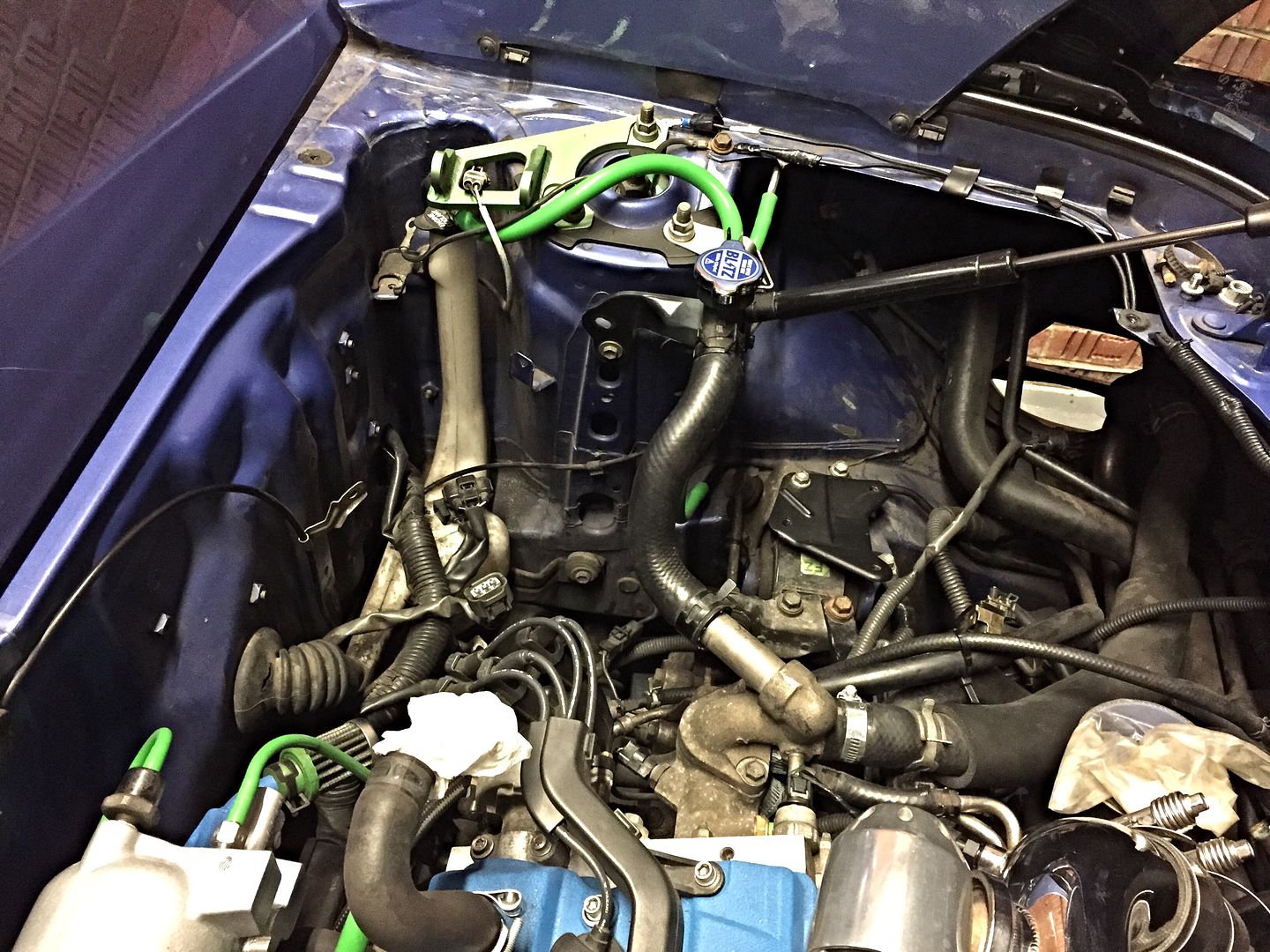
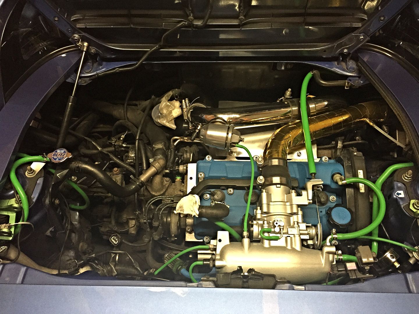
still a work in progress, but least car is drivable now.
i still have more to do, mini wire tuck, get that coolant elbow and dizzy housing painted, plus more cleaning and hoses to do. but is looking miles better now.

i still have more to do, mini wire tuck, get that coolant elbow and dizzy housing painted, plus more cleaning and hoses to do.
Re: Rev4 Turbo *mini photoshoot*
Love it Jim 
Re: Rev4 Turbo *mini photoshoot*
That's looking very cool and very clean, some serious engine bay envy, currently giving me the inspiration to get round to mine (one day). Out of interest the nut and Bolt set you've replaced, do you have the kit part number?
Re: Rev4 Turbo *mini photoshoot*
it was this bolt kit
http://www.ebay.co.uk/itm/3SGTE-MR2-GT4 ... 33a8de50c0
plus i had to ask for 4 x 42mm and 2 x 115mm from them afterwards (which they were happy to additionally send to me), as those were missing in the kit to make it work with a rev3+ mr2 engine bay.
(kit is likely fine as is for a st205, may even be fine on a rev1/2, i dont know)
http://www.ebay.co.uk/itm/3SGTE-MR2-GT4 ... 33a8de50c0
plus i had to ask for
Re: Rev4 Turbo *mini photoshoot*
few more goodies showed up over the past week.
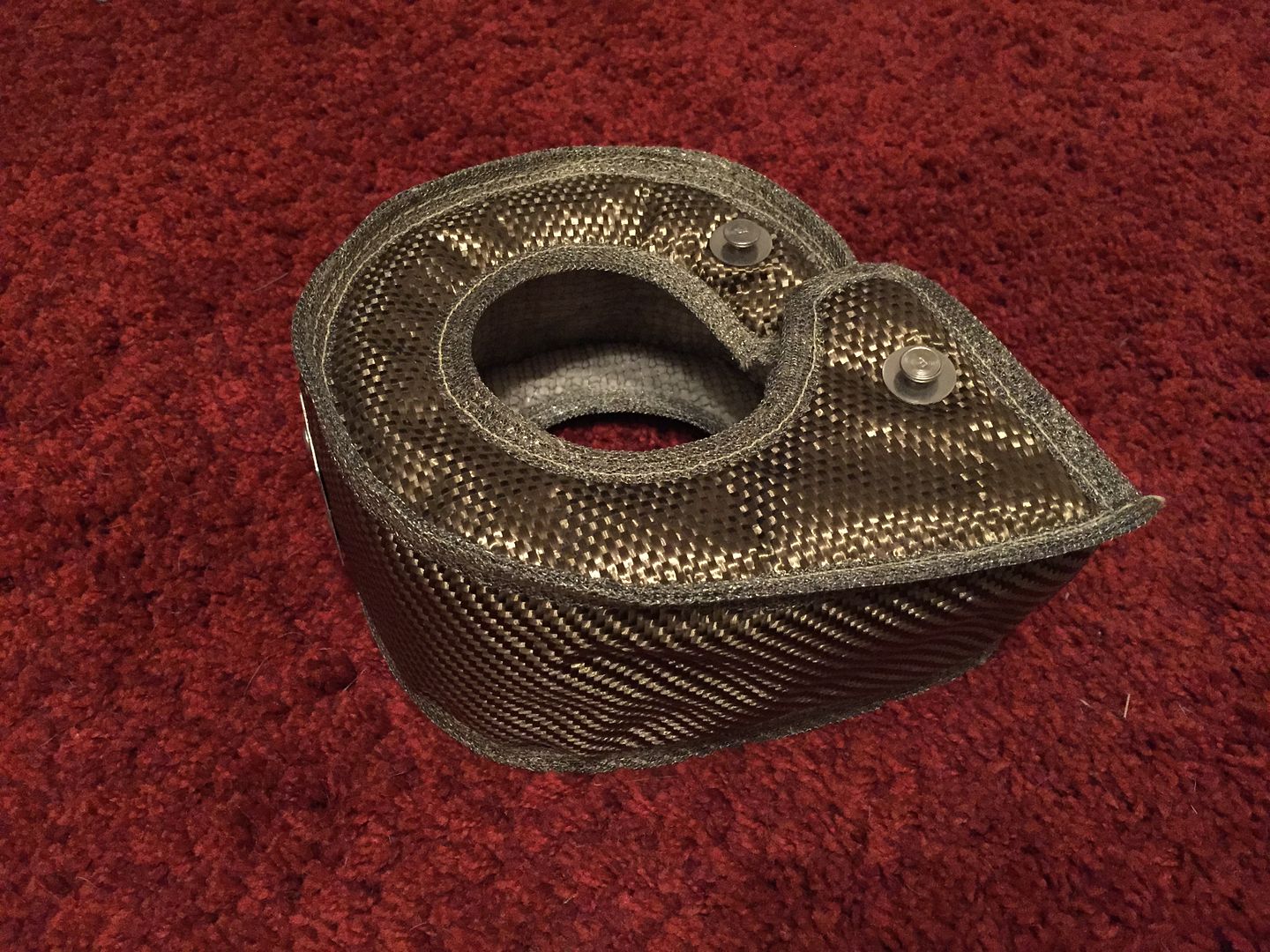
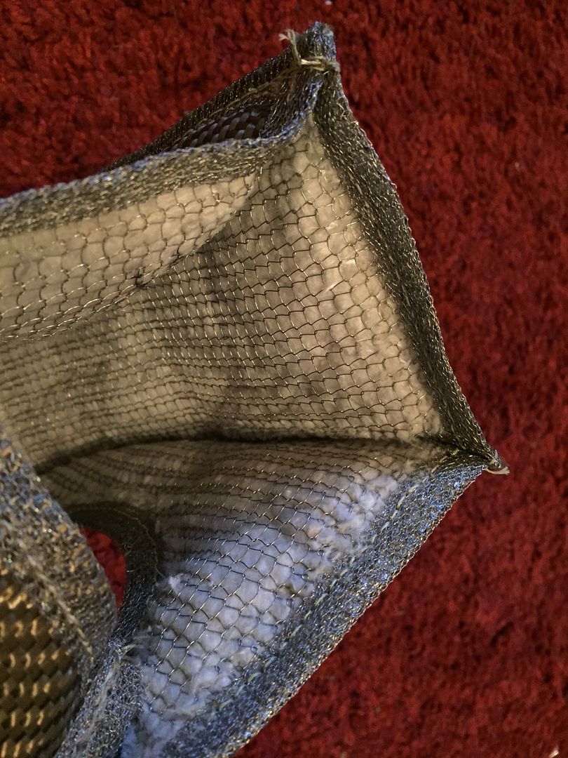
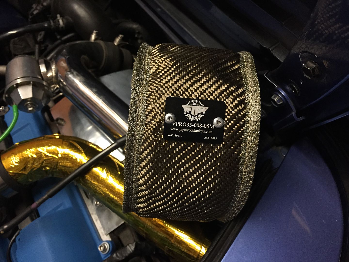
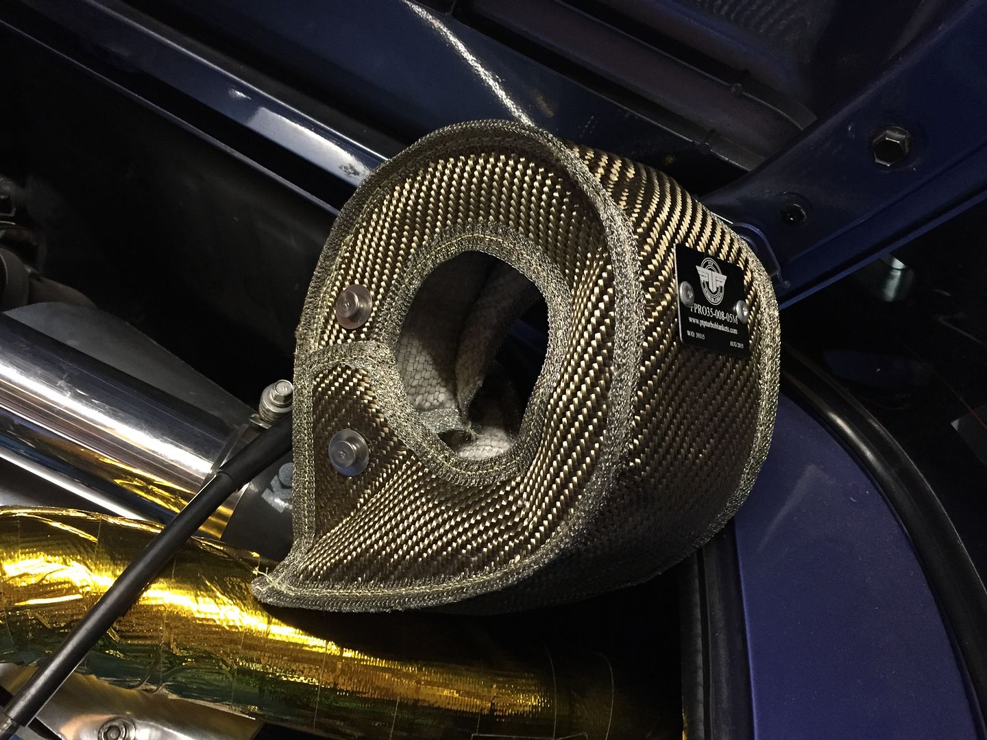
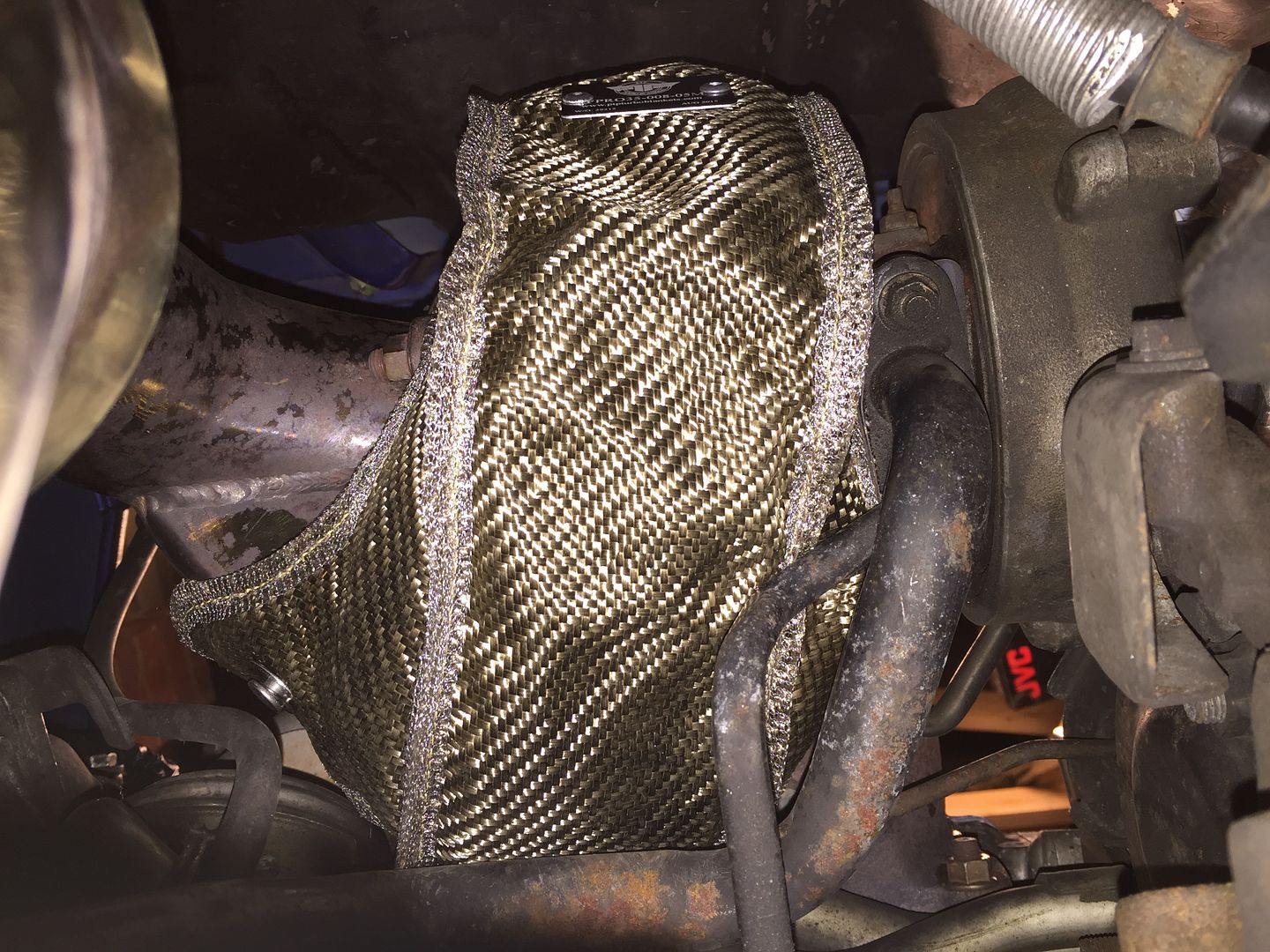
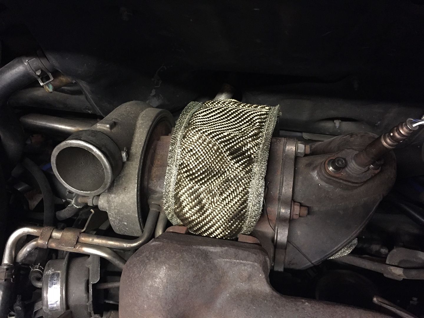
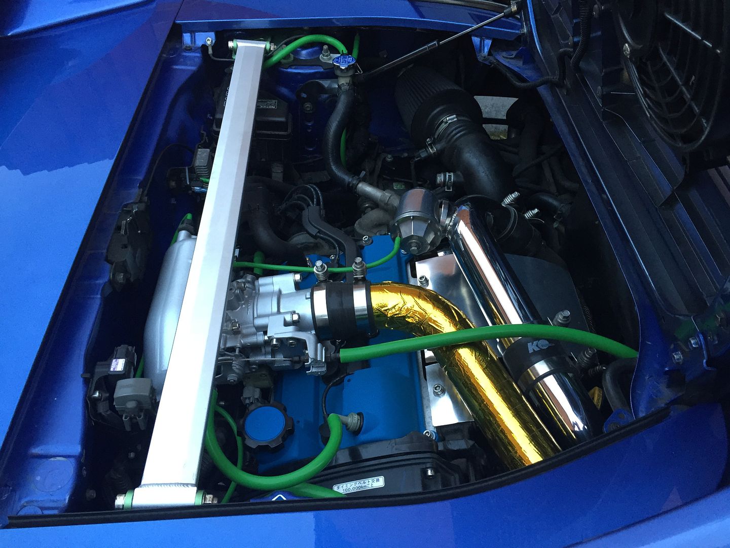
my T3 sized PTP turbo blanket, come highly recommended from the US.
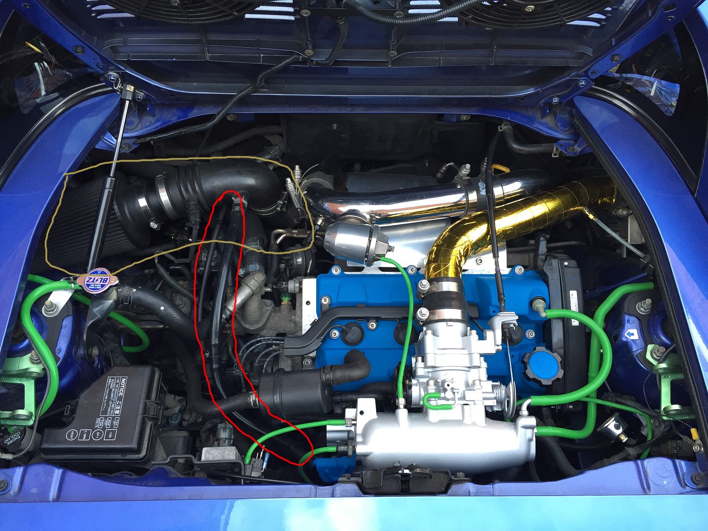
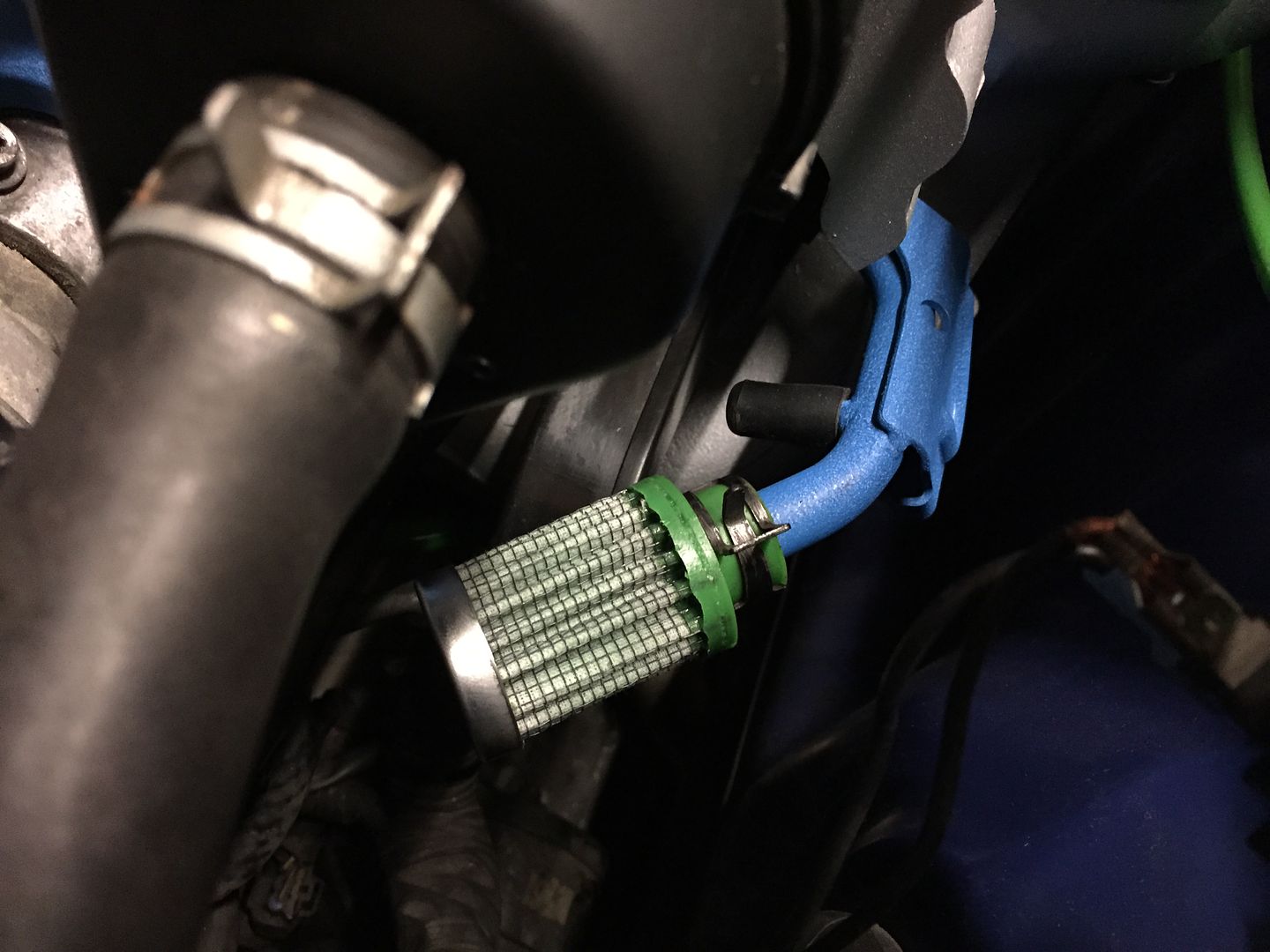
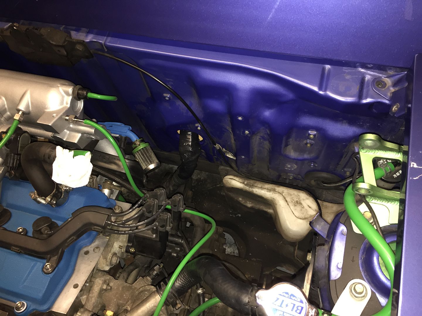
also, after trying to hunt down a green hose for my ISCV, i decided to just do anyway with that line, as its huge, and run a breather filter off the bracket instead.
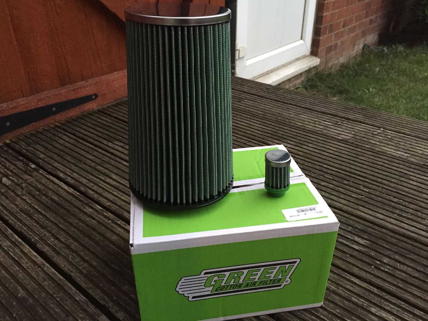
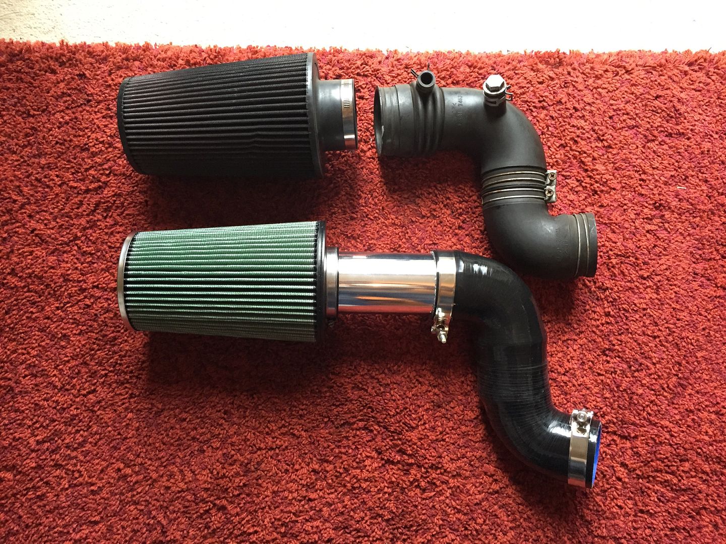
i also got myself a"green" filter set. a huge 6x9 inch jobbie. similar to the KN, oil based, but much less oil by the feel of things! you dont hear many people running the "green" filter, hopefully do me well.
because i was ditching this iscv line, i now had no need for an intake with any holes in. (i can tie up the ait sensor near the intake).
so i set about making a custom intake. not yet fitted but should look really nice!
also on order i have a bunch of stainless clamps for the smaller hoses.
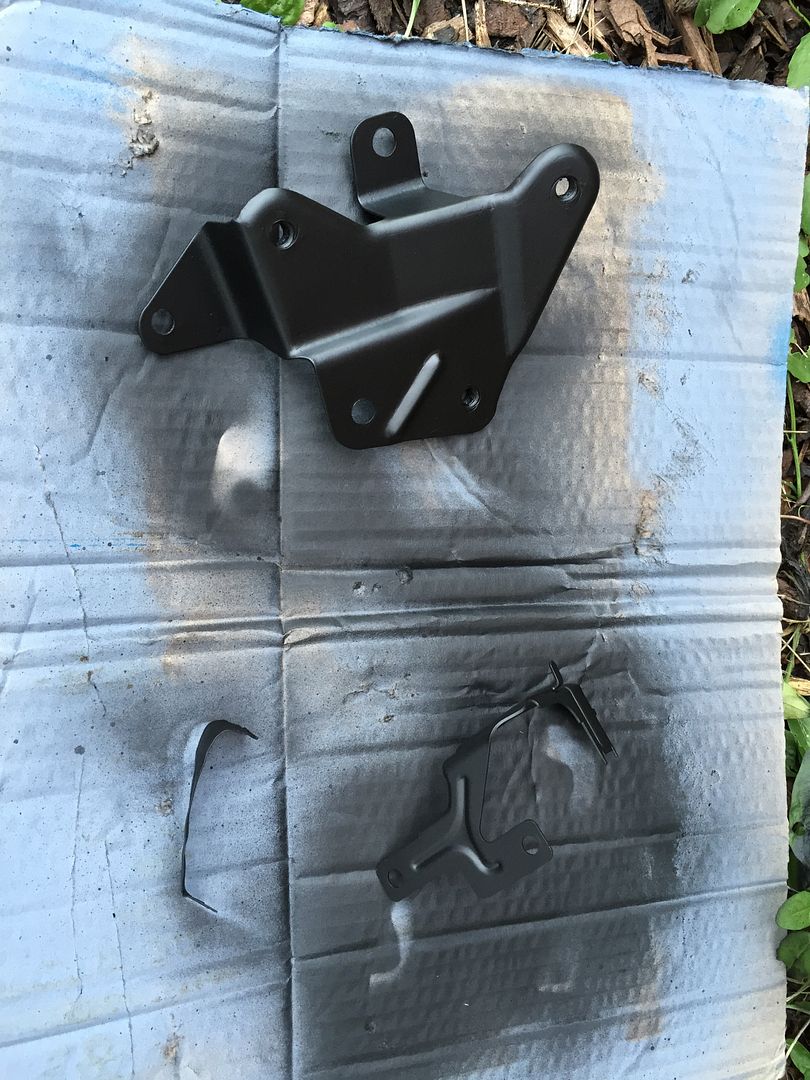
i cleaned up a few brackets matt black while waiting for bits.
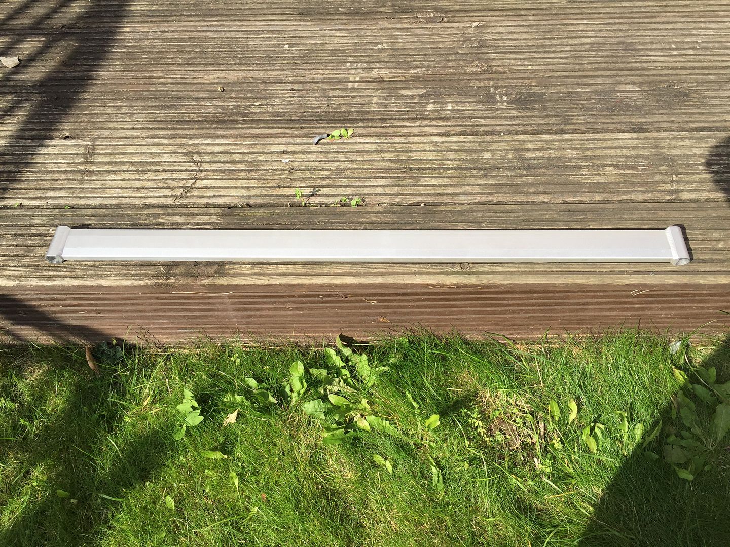
also gave my tein brace a good clean! looks sweet.
areas i wasnt keen on
PTP blanket
tein brace
green filter
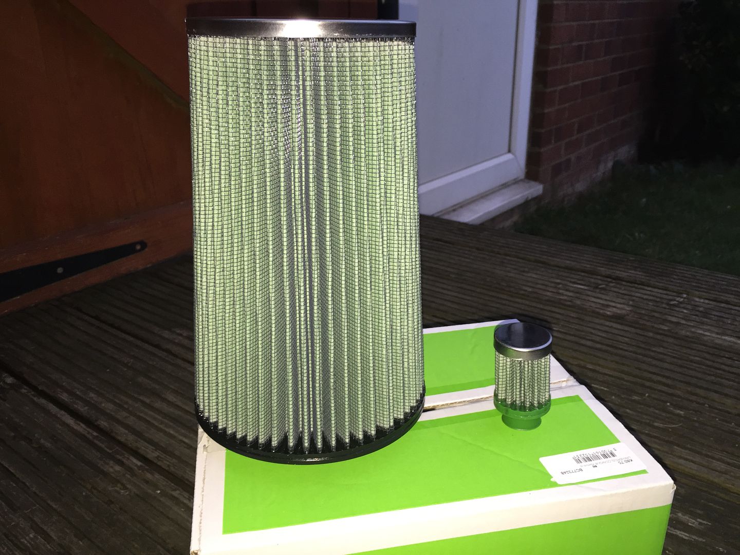
breather location
old and new intake setup!
my T3 sized PTP turbo blanket, come highly recommended from the US.
also, after trying to hunt down a green hose for my ISCV, i decided to just do anyway with that line, as its huge, and run a breather filter off the bracket instead.
i also got myself a
because i was ditching this iscv line, i now had no need for an intake with any holes in.
so i set about making a custom intake.
also on order i have a bunch of stainless clamps for the smaller hoses.
i cleaned up a few brackets matt black while waiting for bits.
also gave my tein brace a good clean! looks sweet.
areas i wasnt keen on
PTP blanket
tein brace
green filter
breather location
old and new intake setup!
Re: Rev4 Turbo *mini photoshoot*
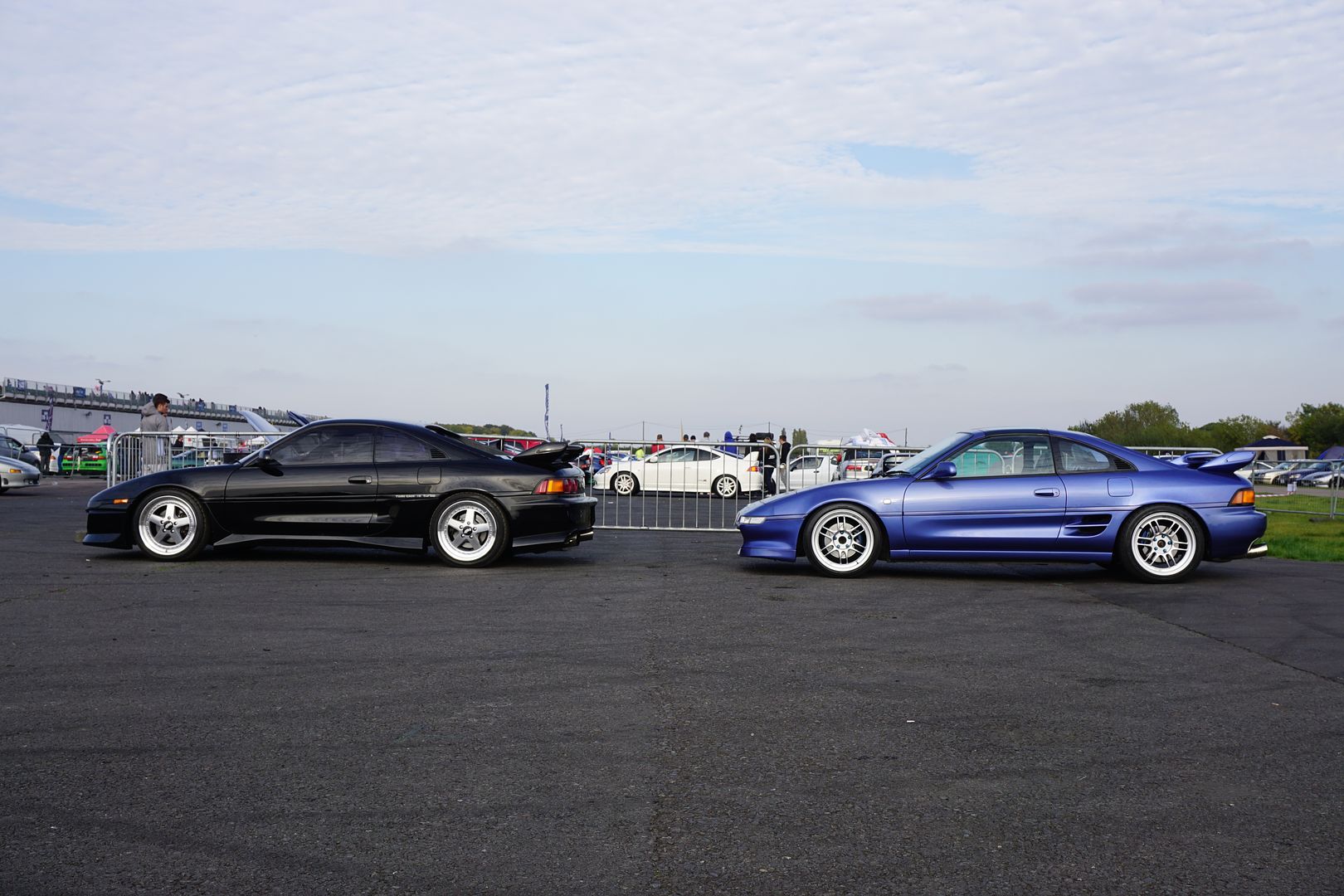
had a pretty busy weekend with the 2!
santa pod the whole of saturday, and another great Kent run on the sunday.
officially shattered, and i bet the car is too!!
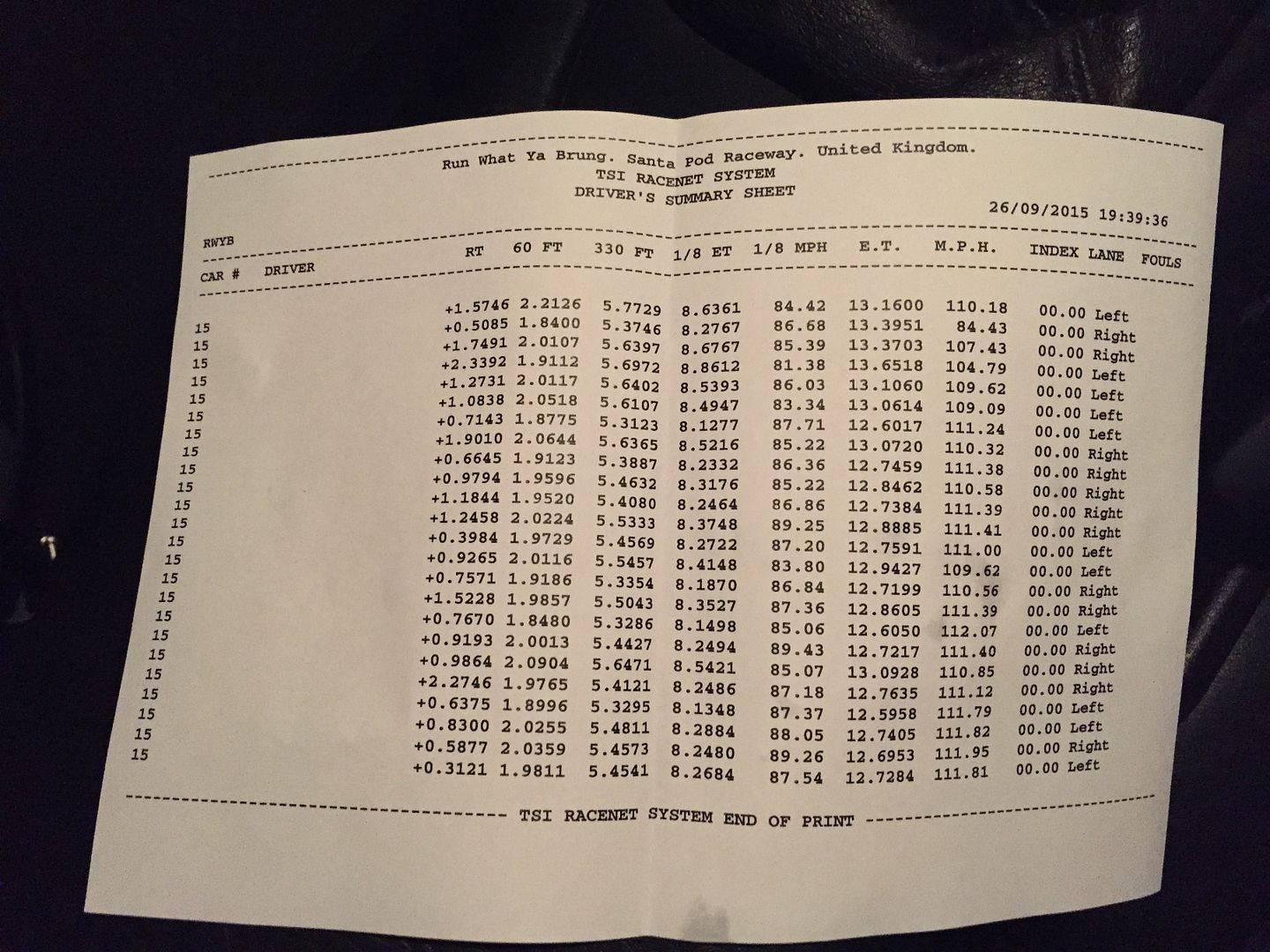
anyways, i managed to get in a hell of alot of runs surprisingly.
my few extra tweaks appear to have worked well.
i had no issues breaking in the 12s most of the day, with the highlights being two 12.60's and im chuffed to bits, a 12.59! officially a 12.5 second mr2! 
most of the terminal speeds were up at well, in the 110-112 area showing ive gained some hp from somewhere.
unfortunately i could never nail down the launch consistently, but overall, over the moon.
i cant see me bettering it without a better clutch, uprated cv's and some dedicated drag wheels. so im going to quit it there for a while.
redynoing the car will probably be a good idea next, see whats its making.
**1/4 mile videos to come!!**
santa pod the whole of saturday, and another great Kent run on the sunday.
officially shattered, and i bet the car is too!!
anyways, i managed to get in a hell of alot of runs surprisingly.
my few extra tweaks appear to have worked well.
i had no issues breaking in the 12s most of the day, with the highlights being two 12.60's and im chuffed to bits, a 12.59! officially a 12.5 second mr2!
most of the terminal speeds were up at well, in the 110-112 area showing ive gained some hp from somewhere.
unfortunately i could never nail down the launch consistently, but overall, over the moon.
i cant see me bettering it without a better clutch, uprated cv's and some dedicated drag wheels.
redynoing the car will probably be a good idea next, see whats its making.

Re: Rev4 Turbo *mini photoshoot*
Thanks, pretty quiet really with the Berk exhaust.
Submitted my times to the registry
Think I'm the only non built car in the top20?? Pretty happy with that given I'm still on a ct series turbo!
I'm only a 10th off Mark Edwards old time, and he was running 1.7+bar on a fully built motor with the ct26 hybrid.
Not sure how much I'm going to push things, I think a better clutch, cvs and maybe look into some 16s with a chunky tyre could well see me in the low 12.3s!
Though a ct20b hybrid is really tempting me to keep things Toyota!
Re: Rev4 Turbo *mini photoshoot*
jimGTS wrote:Thanks, pretty quiet really with the Berk exhaust.
Submitted my times to the registry
Think I'm the only non built car in the top20?? Pretty happy with that given I'm still on a ct series turbo!
I'm only a 10th off Mark Edwards old time, and he was running 1.7+bar on a fully built motor with the ct26 hybrid.
Not sure how much I'm going to push things, I think a better clutch, cvs and maybe look into some 16s with a chunky tyre could well see me in the low 12.3s!
Though a ct20b hybrid is really tempting me to keep things Toyota!
You really are getting some cracking times considering your mods, how does the car feel compared to your 400 bhp car
Did you ever try a quarter mile in that car
You need to get the car stuck on a decent dyno, would be interesting to see what power she is putting out, you removed much weight
Car is looking very nice Jim, wheels are mint.
Re: Rev4 Turbo *mini photoshoot*
Hi Martin, I did.
But could never launch it at all. Always would spin off the line resulting in poor 60ft times. Running 18s on that I guess didn't help.
I only ever got one 12 second pass on that car! A 12.88 at 116mph. Think the 60ft was 2.2.
Soon as I got my 60ft down with better tyres and practice, I ran into gearbox issues from 1st to 2nd. Could never get a clean pass!
I did sort these issues with new gearbox oil and adjusted the clutch, but never went back again before selling it.
I'm confident it would of got low 12s consistently at that point.
Yeh I do need to get the car dynod. I can only guess in the 320 area given mods, but who knows. Trapping 110-112mph the hp must be up there for sure.
I think I've removed 40-50kg from standard. Not a huge amount.
Car was a lot heavier at one point with my ICE and work wheels. So I can't really count those as not part of the stock setup.
But could never launch it at all.
I only ever got one 12 second pass on that car! A 12.88 at 116mph.
Soon as I got my 60ft down with better tyres and practice, I ran into gearbox issues from 1st to 2nd.
I did sort these issues with new gearbox oil and adjusted the clutch, but never went back again before selling it.
I'm confident it would of got low 12s consistently at that point.
Yeh I do need to get the car dynod.
I think I've removed 40-50kg from standard.
Car was a lot heavier at one point with my ICE and work wheels.
Re: Rev4 Turbo *mini photoshoot*
Drag Strip king Jim Are you coming tomorrow?
Re: Rev4 Turbo *mini photoshoot*
I will be there tomorrow. But doubt I'll run. Be quite busy and I'd like to see some others run for once instead of waiting inline.
I would have gone up there today and spent the night and gone to the show on Sunday but don't think I can do anything to improve on my times at present so plenty happy enough for now to not worry about running so only going tomorrow.
You be there?
I would have gone up there today and spent the night and gone to the show on Sunday but don't think I can do anything to improve on my times at present so plenty happy enough for now to not worry about running
You be there?
Re: Rev4 Turbo *mini photoshoot*
Good weather permitting, I'll be there
Re: Rev4 Turbo *mini photoshoot*
Odin_S wrote:Good weather permitting,
bet you didn't see me sneak this in!
Re: Rev4 Turbo *mini photoshoot*
i was going to leave this till winter, but i cant help myself working on it, so the other weekend i decided to start my mini wire tuck....
i got the idea from Karl Withers routing the harness over the passenger side arch.
not only would this mean no worries with repinning, but also ment cabin side everything plugged in at it should!
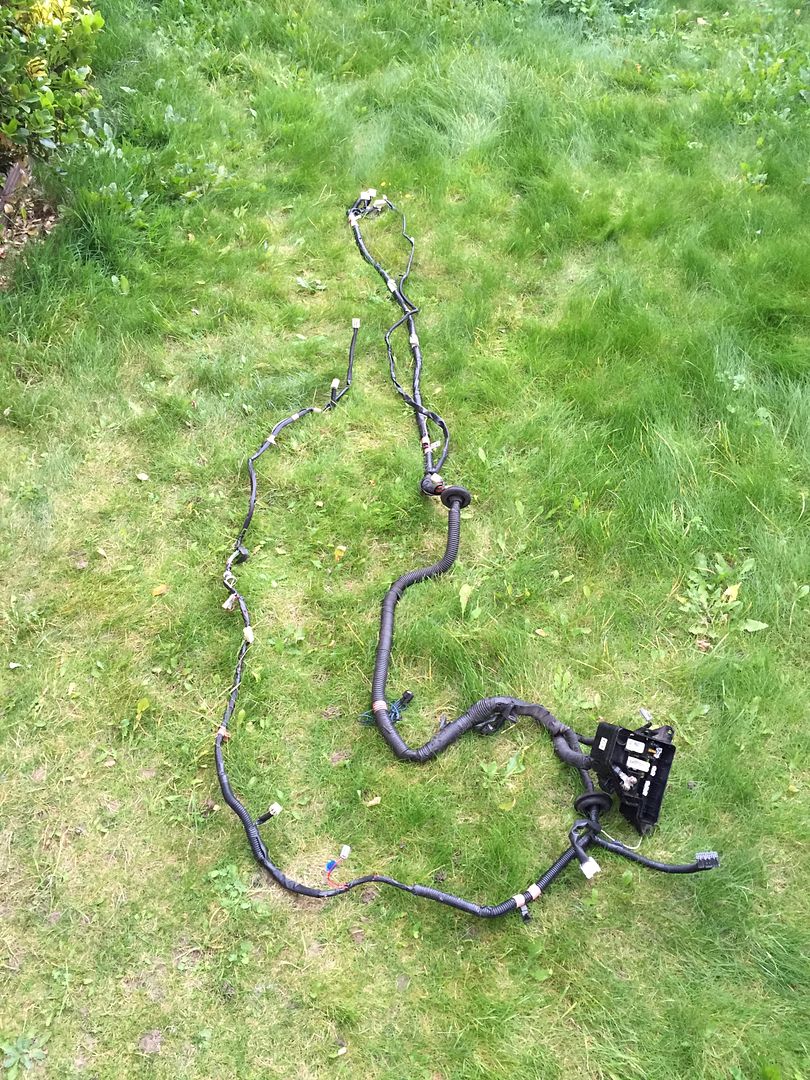
first up, remove the harness, this is from passenger footwell to the ecu.
next up rerouting it over the arch and out through the petrol cap grommet
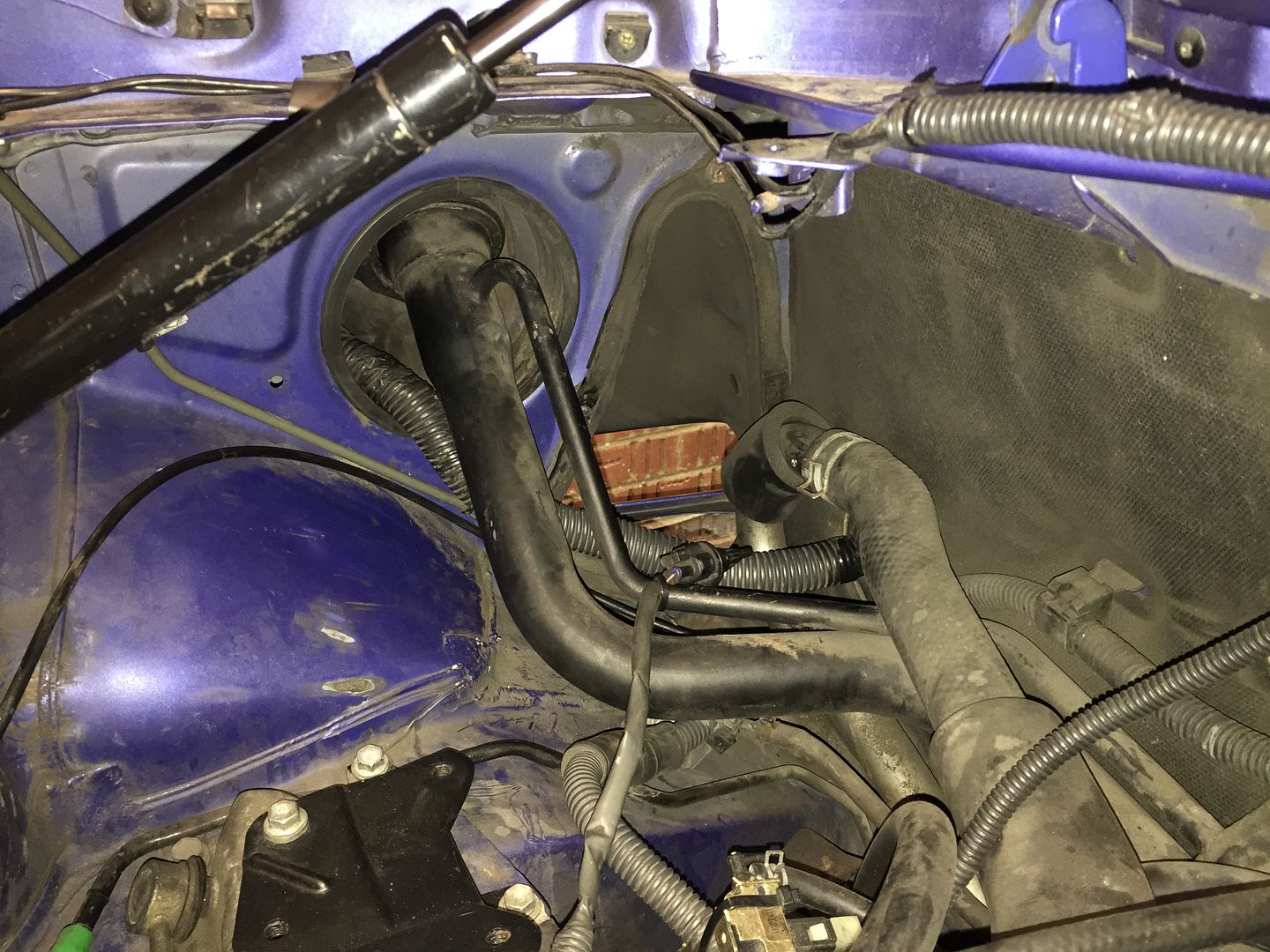
got to this, hell of alot of space passenger side
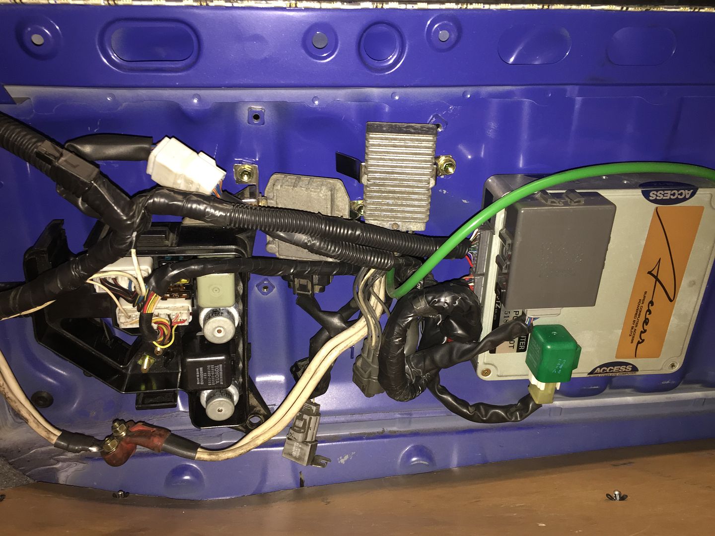
next up tidying the wiring into the boot.
i had thought id need to drill another hole, as stock there are 2 holes for the harness, but the new location for the fuse box and ecu, i couldnt use one of them unless i wanted to extend the wiring, and i said from the off i didnt want to hassle with this.
i soon realised there was potential for the whole lot to fit through the 1 hole!
however it involved pretty much stripping all the old tape/covers off everything engine and boot side, then new taping and bundling them all together.
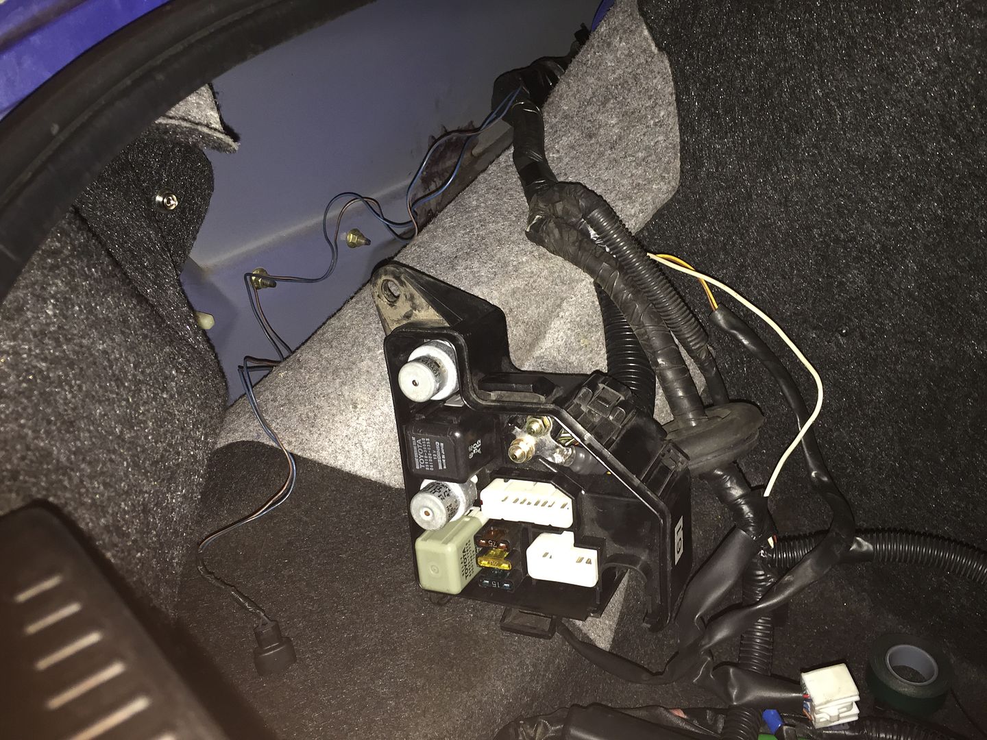
now one tidy harness through the one original hole.
only tweak ive had to make is to modify the back of the fuse box to take the new angle of the loom

ive since tweaked this setup slightly, but only image i have at the moment
to get to this stage involved ALOT of head scratching!!!
working out how long some connector looms were, how stuff would reach etc.
hopefully fingers crossed all with be good.
i still need to;
mount the coil,
fit a longer coil lead
tidy and tape/cover up a couple of looms
i have a braided harness sleeve to put on to cover the whole lot from engine to boot
slice an old vac hose to protect the loom on the firewall, as i had to ditch the oem grommet, first try appears to work great.
in the end i did make use of the 2nd hole by the expansion tank for the ABS sensor, there was not much i could do about this connector to keep it out the bay unless i wanted to drill into the arch liner and arch itself to thread the wire through into the boot, so i made do using the other oem loom hole instead.
i got the idea from Karl Withers routing the harness over the passenger side arch.
not only would this mean no worries with repinning, but also ment cabin side everything plugged in at it should!
first up, remove the harness, this is from passenger footwell to the ecu.
next up rerouting it over the arch and out through the petrol cap grommet
got to this, hell of alot of space passenger side
next up tidying the wiring into the boot.
i had thought id need to drill another hole, as stock there are 2 holes for the harness, but the new location for the fuse box and ecu, i couldnt use one of them unless i wanted to extend the wiring, and i said from the off i didnt want to hassle with this.
i soon realised there was potential for the whole lot to fit through the 1 hole!
however it involved pretty much stripping all the old tape/covers off everything engine and boot side, then new taping and bundling them all together.
now one tidy harness through the one original hole.
only tweak ive had to make is to modify the back of the fuse box to take the new angle of the loom
ive since tweaked this setup slightly, but only image i have at the moment
to get to this stage involved ALOT of head scratching!!!
working out how long some connector looms were, how stuff would reach etc.
hopefully fingers crossed all with be good.
i still need to
mount the coil,
fit a longer coil lead
tidy and tape/cover up a couple of looms
i have a braided harness sleeve to put on to cover the whole lot from engine to boot
slice an old vac hose to protect the loom on the firewall, as i had to ditch the oem grommet, first try appears to work great.
in the end i did make use of the 2nd hole by the expansion tank for the ABS sensor, there was not much i could do about this connector to keep it out the bay unless i wanted to drill into the arch liner and arch itself to thread the wire through into the boot, so i made do using the other oem loom hole instead.
Last edited by jimGTS on Thu Oct 29, 2015 5:55 pm, edited 1 time in total.
-
danthevanman
- Posts: 84
- Joined: Wed Jun 23, 2010 7:02 pm
Re: Rev4 Turbo *mini photoshoot*
I'd use the stuff in the link below and some super glue instead of the vac lines for protection.
It comes in different widths so you'd have to check how thick the metal edge is.
http://www.ebay.co.uk/itm/Grommet-Strip ... SwnDZUH97x
It comes in different widths so you'd have to check how thick the metal edge is.
http://www.ebay.co.uk/itm/Grommet-Strip ... SwnDZUH97x
Re: Rev4 Turbo *mini photoshoot*
danthevanman wrote:I'd use the stuff in the link below and some super glue instead of the vac lines for protection.
It comes in different widths so you'd have to check how thick the metal edge is.
http://www.ebay.co.uk/itm/Grommet-Strip ... SwnDZUH97x
that looks ugly!
given im using the oem holes, everything is already smoothed/painted, so nothing should
and with the lip with the hole
though thats not to say i dont appreciate the suggestion.
if theres something less ugly, i may look into that.
-
danthevanman
- Posts: 84
- Joined: Wed Jun 23, 2010 7:02 pm
Re: Rev4 Turbo *mini photoshoot*
I used the stuff in the previous post before but sealed over the edge and filled in the hole with black rubber seal / silicone so that the cables wouldn't move and it would be watertight.
It does come in this form aswell.
http://www.ebay.co.uk/itm/321884101702? ... EBIDX%3AIT
It does come in this form aswell.
http://www.ebay.co.uk/itm/321884101702? ... EBIDX%3AIT