I don't think there is a distinction between analogue and digital outputs

(although there is for inputs).
The LEM doesn't anyway.
You should be able to use any
"Auxiliary Output" for this.
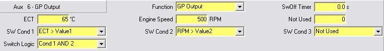
I've set mine up as follows:
As for the wiring, that should be as follows:
+12V switched
--->
(~2A) Fuse
---> Relay coil
--->ECU
"Aux Output"
+12V
---->
(~30A) Fuse
---> Relay load
---> Earth
You can use the
(permanent)
+12V supply from the main fuse box for the fan side of the relay, but you'll need to take a switched
+12V for the relay coil.
If you use the main live from the fuse box for the relay coil then the fans will come on whenever the ECU shuts down.
Check with a multimeter but you should be fine to use the same wire as feeds power to the ECU.
It sounds like you're more than capable of finding that if you've made the loom yourself though.
The ECU can provide a ground for the relay switch, but as mentioned above it will only accept a low current.
Check in your LINK manual to be on the safe side but for reference, my ECU can can deal with a relay provided the resistance of the coil is 7A or more.
The relay coil will be plenty more than that but again, check it with a multimeter.
(disclaimer over

)
I'm sure i've made it sound harder than it is but I couldn't face trying to draw circuit diagrams in paint!
Wingers